


Collaboration between electrical and mechanical design just got easier with SOLIDWORKS PCB
Traditionally, electrical and electronics design have been separated from mechanical design. Electrical engineers or designers completed electrical projects, while mechanical engineers or designers executed mechanical projects. However, as products and designs continue to innovate, we have been seeing more and more electro-mechanical systems or mechatronic systems.
As this complexity and collaboration between the mechanical and electrical worlds continues to advance, we need our design software to advance with it.
In the past, there was no easy way for electrical design teams to work with mechanical design teams
The traditional design and development process of mechatronic systems included an electrical team working on the electrical design then exporting this over to the mechanical team. The mechanical team imported the electrical design, made whatever changes or comments were required, and then they exported it back over to the electrical team. This process would continue for many iterations with lots of importing and exporting back and forth. A lot of time was wasted waiting for reviews or updates.
In this situation, updates weren’t taking place for both teams in real-time, which could lead to additional design mistakes or errors. Plus, a lot of design time was lost due to the importing and exporting, as well as waiting for the other team to finish off their portion of the work.
Thankfully, SOLIDWORKS PCB has come up with a great solution for this exact problem.
SOLIDWORKS PCB provides real-time collaboration between electrical and mechanical engineering design teams
SOLIDWORKS PCB offers the ultimate full-design solution for any mechatronic system needs. Users can generate professional electronics and PCB schematics, PCB layouts, and manufacturing reports, leveraging real-time integration and collaboration between electrical and mechanical design.
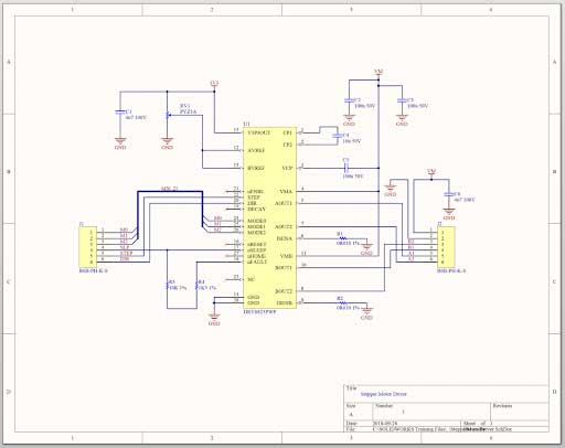
Looking at Figure 1, you can see a PCB schematic created with SOLIDWORKS PCB that includes
- All electronic components
- Schematic symbols
- Wiring
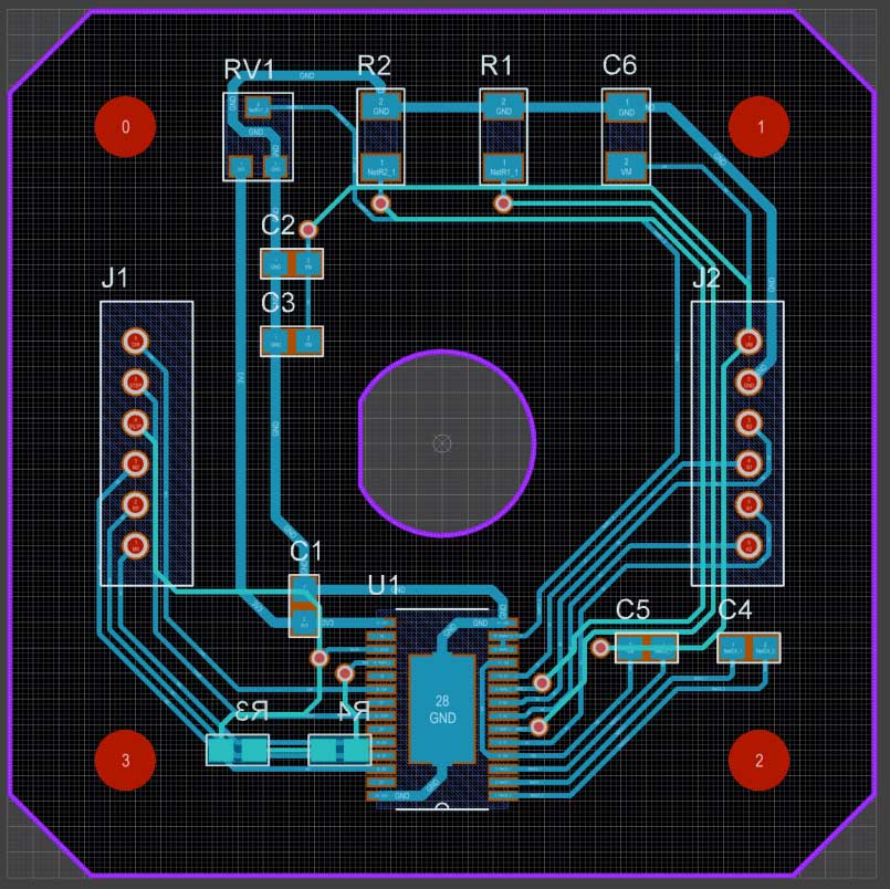
Once you’re happy with the schematic, you can push the entire design over to the PCB layout
The PCB layout (figure 2) is used to define the board shape, including any mounting holes or keep out areas, as well as the placement of each electronics component and the routing of electrical traces between these components. The PCB layout is usually very important in the design process for both the electrical and mechanical design teams, as many projects must fit these PCB boards into very specific areas or enclosures that might have tight tolerances or very specific mounting locations.
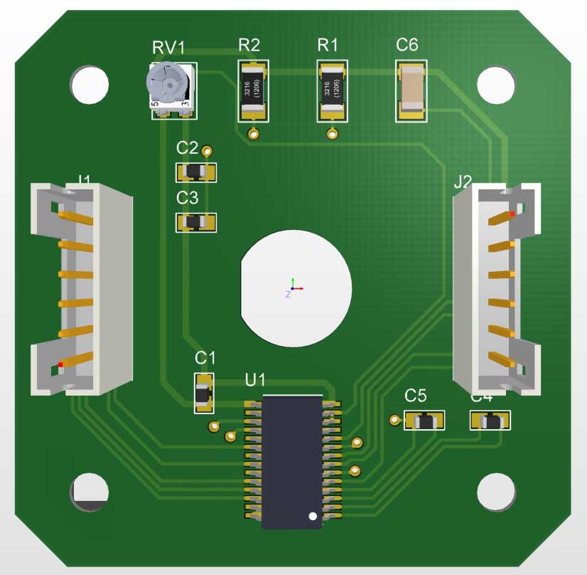
Edit and navigate your PCB layouts in both 2D and 3D views
Editing and navigating your PCB layouts in both 2D and 3D views (figure 3) can help you visualize your final products and view potential mechanical clearances and electrical clearances.
With SOLIDWORKS PCB, electrical and mechanical teams get real-time access to project files
A general full electro-mechanical process might start with the electrical or electronics design to create the PCB schematic and PCB layout. Once the electrical team is happy with their design, they might then push this over to the mechanical team. The mechanical team will then try to mount or attach the PCB to the mechanical assembly or enclosure. If the PCB does not fit perfectly with the mechanical design, the mechanical team can suggest or make some mechanical changes or modifications to the existing PCB layout. They will then push these changes back to the electrical team.
This is the power behind SOLIDWORKS PCB: the integration and collaboration between electrical and mechanical design. Each team has direct, real-time access to the project files, and they can be pushed and pulled between ECAD and MCAD.
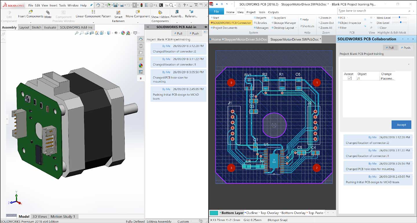
These changes are automatically updated in real-time to both teams, and each team can view the suggested changes and accept — or not accept — these changes. Posts with date and timestamps can also be shared right within the PCB collaboration panel so the teams can chat with each other to advise what changes can occur.
Figure 4 is an example of the initial design the ECAD team pushed to the MCAD team. The MCAD team then made a few small changes, including changing the mounting hole sizes and moving some electronics components around the board. The MCAD team then pushed this back to the electrical team who saw these changes and had the option to accept or reject.
This back and forth happens constantly within any mechatronic design project. With the help of SOLIDWORKS PCB, teams will experience huge time savings and cost savings resulting from the vastly improved collaboration between multiple teams.


