


Get started with Inventor advanced part design by learning the 3D sketch environment and tools.
Creating 3D sketches in Autodesk Inventor takes a little bit of practice but it’s a valuable time-saving skill to have, especially if you’re designing frames, tubing, or piping. In this Inventor tutorial, we’ll walk you through how to get started with 3D sketching for advanced part design.
To begin an Inventor 3D sketch, simply click the Start 3D Sketch button on the ribbon. At first, not much will look different between the 2D sketching and 3D sketching environments. Many of the same sketch tools are available in both sketching environments including lines, arcs, and splines.
There are two new commands available in the Inventor 3D sketching view: Bend and Point. Bend performs a function similar to a fillet for 2D sketches. The Point command allows you to create points in 3D space that can be used to connect geometry in ways that wouldn’t be possible in a 2D sketch.
How to make a line in an Inventor 3D Sketch
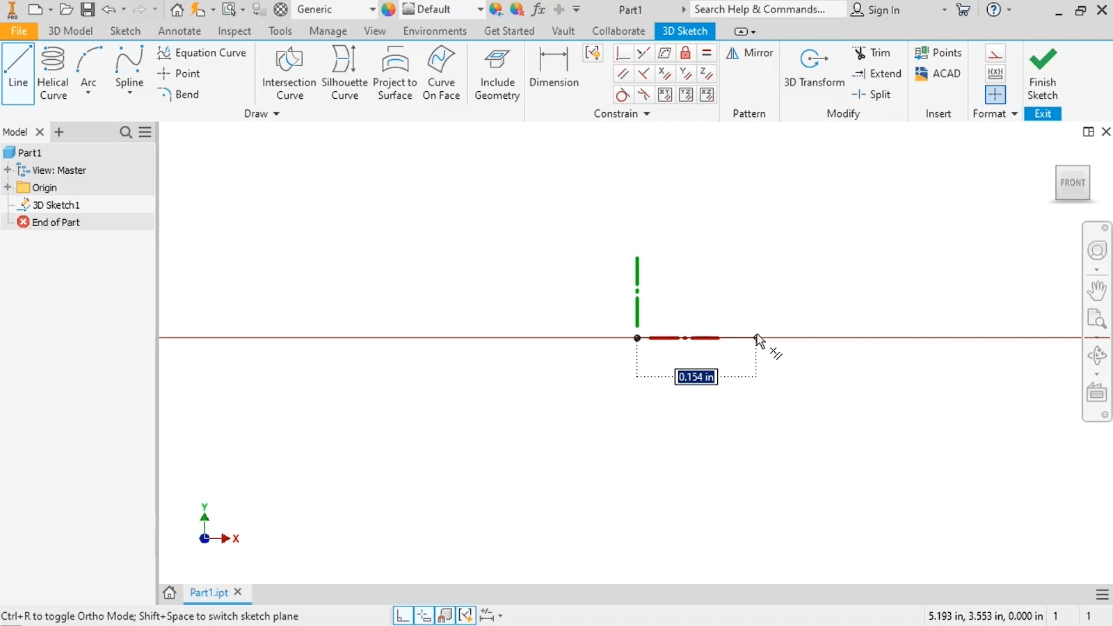
To learn how to make a line in a 3D sketch in Inventor, let’s start with the basics. First, activate the Line command from the ribbon. Notice that the dialog box attached to the cursor tells you exactly where in a 3D space you are and allows you to input XYZ coordinates to precisely place a point.
To get more control over both the coordinates and the triad, you can expand the Draw panel and select Precise Input to bring up the toolbar.
With Precise Input, you can still input the starting coordinates for the line, but there are a few additional functions.
- Reset to Origin will reset the user coordinate system to (0,0,0) when you click it while using an Inventor 3D sketch tool. This can be helpful if you have a large and complex 3D sketch and need to start a new command from the origin.
- Reposition Triad will move the triad to a specified coordinate. This function is helpful when you need to draw multiple parallel lines that aren’t in the same plane.
- In the drop-down under Reposition Triad, you can select either Relative or Absolute to specify how the coordinates will be referenced. Relative starts the sketch segment based on the last point entered, while an Absolute start is based on the origin. If you know the location of a point in relation to a previous point, use Relative. If you know the precise XYZ values, use Absolute. Practice both methods!
Precise Input can be used at any time. If you start a free-handed sketch and want to add a line segment at a precise location from your last drawn point, you can type that value into the dialog box, press Enter, and continue drawing as before.
Once the start of the line is created, you can click anywhere or enter a point into the Precise Input toolbar to create a second point.
Like this Inventor tutorial? Check out our full Inventor training library >>
More Inventor 3D sketch tools to know
There are a few more tools to learn that can make it easier to work with 3D sketches in Inventor.
Inventor 3D Sketch Tool, Ortho Mode
Along the bottom of the interface, you’ll see a few icons that you can toggle on or off.
- Ortho Mode restricts the cursor’s movement to the X, Y, and Z directions. With this enabled, Inventor will only let you create the line horizontally or vertically, not diagonally.
- As you continue sketching, a dynamic dimension box appears next to the line. You can turn this off by toggling the Dynamic Dimension option.
- Snap Object gives you the option to enable or disable object snaps, which let you snap onto existing geometry.
- Infer Constraints lets you apply constraints automatically as you’re sketching, like a coincident constraint.
- You’ll also find Show Constraints, Hide Constraints, and Display Tolerances here.
Bonus hint: try activating grid lines when working in the Inventor 3D sketching environment. Grid lines allow you to better approximate the lengths of sketch segments you create. To do this, go to Tools → Application Options → Sketch → check the box next to Grid Lines under Display → click OK to accept the changes.
Did you find this Inventor tutorial helpful? Explore over 1,000 more Autodesk Inventor video tutorials in the SolidProfessor library.