


With rising pressure to innovate products and refine processes faster than ever before but without sacrificing quality, engineers face steep challenges in the work they perform.
Engineering design tool developments aim to ease these headaches by managing complexities while increasing productivity and collaboration. For example, the inaugural Pulse of Engineering survey by IHS Engineering360 found that fewer than half of respondents (46%) say that technology was improving their productivity. This aligns with the notion that, despite sizeable recent investments in R&D and enabling technology, companies are not actually more productive.
This overview of technologies explores capabilities, benefits (and potential roadblocks) and best practices in equipping proficient, inventive engineering design teams.
Computer-aided Tools
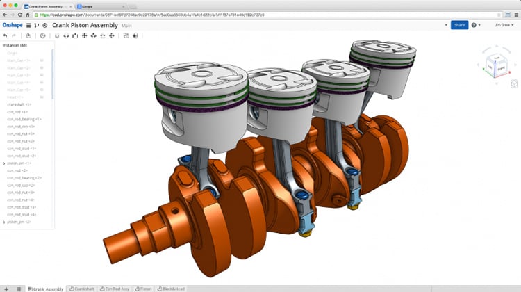
Computer-aided design (CAD) software and computer-aided manufacturing (CAM) software represent the most common platforms in an engineer’s design toolbox. At its most basic level, CAD software allows engineers to create, analyze and share conceptual 2D or 3D drawings for assessment and approval. CAM software, in turn, lets designers leverage CAD data and control automated machinery.
“CAD and CAM greatly allow manufacturers to innovate due to the ability to try a wide variety of different approaches to a product or design quickly,” says Tony Glockler, co-founder of SolidProfessor, which trains engineers, designers and students on multiple CAD and CAM platforms.
CAD system functions extend beyond design. Manufacturing tolerance and cost analysis, photo-realistic rendering and validation of a virtual model in its intended environment are now common place and expected in the design process, says Glockler.
CAD and CAM software also allow users to send their digital prototypes directly to 3D printers and create physical models of a part or assembly. This process, also known as additive manufacturing, uses material such as thermoplastics and metals to craft low-cost prototypes to verify function, ergonomics and other properties that a CAD drawing alone cannot assess.
In the broader scope of engineering design tools, computer-aided engineering (CAE) is an umbrella term for the simulation, validation and optimization of products and processes. Supported tasks include finite element analysis (FEA) to calculate displacements and stresses of components under loads, multibody dynamics to study the kinematics of moving parts and computational fluid dynamics (CFD) to analyze fluid flow characteristics. Many of these capabilities are included with or offered as plug-ins to CAD software.
Among the most common CAD software vendors are SOLIDWORKS, Autodesk and PTC Creo Parametric (formerly Pro/ENGINEER), all of which have multiple software titles that complement or enhance their CAD offerings. Popular CAM platforms include GibbsCAM, Mastercam and CAMWorks.
Collaborative Capabilities
Perhaps the biggest change in CAD/CAM software over the last decade has been the ability for engineers across multiple disciplines to collaborate in a single environment, Glockler says.
He cites the complexity and constraints in designing a smart phone as an example of multidisciplinary collaboration. In particular, mechanical and electronics engineers are responsible for separate components that need to work together.
“You’re addressing what had been, separate software capabilities for each of those disciplines and offering more interoperability, whether that is exchanging files or actually working in the same environment in real time,” Glockler says.
Despite the promise of collaboration, companies are still determining how best to share CAD data. Nearly 80% of respondents to a recent survey from the CAD industry publication Cadalyst say their organizations use e-mail to share and collaborate with CAD files. In addition 72% reports, collaborating via shared folders on a server, while 47% say they use FTP servers. Other challenges identified by survey respondents include unreliable file synchronization, slow network performance and difficulty sharing files externally.
These file-collaboration techniques lack automation to track and maintain file versions, thus requiring manual upkeep. In addition, they potentially can disrupt project workflows and undermine any productivity gains. Glockler says that file management or collaboration systems such as product data management software can overcome many of these challenges.
One major obstacle to engineering design teams not harnessing the full power of CAD, says Glockler, is the training issue, “people are not aware of or knowing the full extent of the capabilities or understanding how to use them properly or consistently across an entire team.”
As another method to promote collaboration, many CAD software vendors offer accompanying applications for use on a mobile device. These apps enable engineers to view, annotate and share their 2D and 3D drawings. A relatively new player in the market, Onshape, offers CAD exclusively in the cloud.
Math, Physics and Mechatronics
Many engineering design projects and products require more than the static models available from CAD software. Graphical programming platforms such as LabVIEW from National Instruments and MathWorks’ MATLAB Simulink address this drawback by allowing engineers to simulate a multi-domain system — one that integrates physical and software components — without needing to code by hand. The coding is done graphically both for simulation and real-time applications. In practice, users plug in a block diagram of their design and automatic code generation simulates its behavior. Based on the simulations, engineers can test, refine and validate their designs.
This model-based design is at the heart of creating mechatronic systems. Used in everything from automobiles to biomedical devices, mechatronics integrates mechanical, electrical, control, and computer components.
Model-based design manages the complexities of mechatronic designs yet faces obstacles in wider deployment. In many companies, for example, electrical, mechanical and computer control engineers still work in silos.
“They have a great understanding and insight into how things work, but often it’s not something they could document or communicate to someone else based on experience,” says Kevin Craig, professor of mechanical engineering and a mechatronics specialist at Hofstra University’s School of Engineering & Applied Science.
One reason for this is the lack of math and physics in the design. These two disciplines have been pushed to the engineering back burner because “progress has been defined by building things instead,” Craig says.
A virtual model-based design environment created within the likes of LabVIEW and MATLAB Simulink uses a mathematical and physics approach. Engineers who use these programs don’t have to hand code, as the result often is a shorter learning curve.
As Craig says, “with graphical programming, everyone can do it, and everyone can understand it.”
Avoid Complacency
To ensure the continued measurable success of engineering design tools, organizations can implement a few strategies. One is to stay on top of software, which evolves so rapidly that “if you’re not looking at training as an ongoing need, you are going to fall behind,” SolidProfessor’s Glockler says.
In an ideal world, says Hofstra’s Craig, companies might even take a break from building anything for a few months “to give their engineers time to think, to understand, to simulate and get insight. And when they do build again, it will be smarter, cheaper, faster and work the first time.”


