


The importance of design strength and constructability in SOLIDWORKS weldments
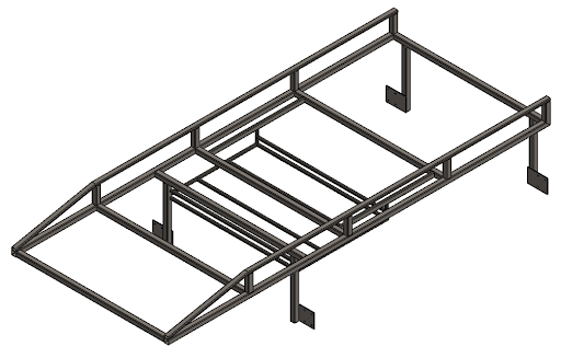
Designing SOLIDWORKS weldments is a great way to generate a frame or chassis, which is often used as the highest strength-bearing component of the assembly. To ensure your design will hold up to the test, you’ll need to make sure the weldment structure can be designed using the right weldment profiles that are oriented properly. For example, some of the bars used in the lumber rack image below are rectangular in cross-section, which is stronger in bending along the length of the longer edge, rather than the shorter edge. Not only does orientation change the strength of the design, but the thickness of the SOLIDWORKS weldment profiles also affect how strong each member will be.
It’s also important to consider how the members will be constructed and joined together. If you’re using an irregularly-shaped cross section, or if the sides vary greatly in length, then joining them together using welds, gussets, and reinforcing plates can be a challenge. This impacts the strength of your model and makes it difficult to figure out how to get the weldment members to connect.
All these factors can lead to you wanting to create a custom weldment profile that suits your exact needs. While this can create the exact design you’re looking for, there’s a number of considerations to take into account when you’re determining the size and shape of the SOLIDWORKS weldment profiles.
Design scenario considerations for SOLIDWORKS weldments
Because the SOLIDWORKS weldment profiles factor into how the entire weldment geometry’s designed, constructed, and performs, there are a number of considerations to take into account. Let’s dive into how the weldment members curve and join together, how they bear weight and undergo loading, and how difficult the members will be to manufacture.
How to curve weldment members and join them together
SOLIDWORKS weldment profiles determine multiple factors about the geometry. Creating unique lengths, angles, and curvatures along the cross-section typically result in a more complicated geometry. For example, if you’re using a unique cross-sectional profile to create a curved member, will bending that member to create the curvature end up distorting the cross section?
You have to be sure that the design in SOLIDWORKS won’t be self-intersecting along the curved path. You also don’t want the bends in the member to lose strength because the cross section is distorting. For instance, if you’re using an Angle Iron for the cross-section, which is an L-shape, will the bend in the cross section remain at 90 degrees? Or will bending that section of the member make the angle closer to 100 degrees? How will this change its strength? How will this area interact with other geometry? It’s important to make sure that curved weldment members aren’t compromised as a result of creating custom SOLIDWORKS weldment profiles.
One of the most important geometry considerations is how the weldment members will join together. When you have custom-shaped SOLIDWORKS weldment profiles, it can become increasingly difficult to join them together. This is especially true when you have three or more members meet at a corner or junction in the design. Oftentimes chassis and frames have four to six members joining together at one point in the model. Predicting how these members will join together is important in creating the right weldment profile.
You’ll have to ask yourself some questions: will they join and be fully connected to one another? Are there parts of the cross-section that won’t be able to be welded properly? How will this affect the joint’s strength? Does there need to be space left for plates bolted on or other reinforcing pieces added? If bolts are used to connect them, will there be enough room for them to slide in and be fastened on the other side? Simplifying SOLIDWORKS weldment profiles as best as possible will greatly improve these situations. Whether that’s making the sides of the profile more evenly spaced, using more uniform angles, or using equally-sized curves, getting your weldment members to align properly guarantees your design will perform at its peak.
Weldment member strength under loading
Weldment design strength is directly determined by the orientation and sizes of its members. Therefore, creating members that undergo loading and distribute stresses to the proper locations is a critical part of designing a cross-section profile. Not all weldment members are weight bearing, but if you’re designing a structure that experiences significant loading, then you’ll need to make sure it’s strong enough.
Performing a Finite Element Analysis (FEA) study is a step in the right direction, but what if your results show it needs improved strength? How will you go back and edit the design? Will changing the member lengths be enough? What if you can’t adjust the lengths or how the members join together? You may need to change the size and shape of the weldment profile to beef up the model. Using thicker and more uniformly shaped cross-sections often helps in areas of high stress, which might mean simplifying your profile as much as possible. This is especially true if the member is experiencing particularly high shear stress (bending) or twisting, as opposed to axial stress.
As you may know, there’s a large variety of ways that weldment structures can deflect, deform, and buckle under excessive forces. Therefore, you’ll want to design your weldment profile in such a way that you can minimize these catastrophic scenarios.
Considerations for manufacturing custom weldment members
As you may expect, manufacturing custom SOLIDWORKS weldments could be difficult and costly. You’ll need to contact a vendor to discuss which aspects of a custom weldment member are most difficult to fabricate, but there are two considerations you should take into account along the way.
- Consider if a standard weldment member can be modified to create the one you’re looking for. For example, you could take a C-channel member and cut one side of it down to make it shorter. This may take a few different operations to get to the finished product — each of which adds cost and time to the fabrication process.
- By contrast, another consideration is if you need to create new weldment members from scratch because you can’t modify existing pieces. Because these are going to be more expensive and take longer to create, you’ll need to know exactly how many members you’ll need to create and how long each will be. There may also be really unique features in the profile that are difficult to create, such as bends and corners that require custom manufacturing methods. Custom member types are always going to drive up cost, the number of processes, and total fabrication time. It’s merely a matter of how many custom features you need and can incorporate into your weldment design without overextending the project parameters.
How to create custom SOLIDWORKS weldment profiles
It’s important to take multiple factors into account when creating the sketch for a weldment profile. Aspects of the sketch, including orientation, proportions of edges and radii, and section thickness will produce drastic changes in results in the final design.
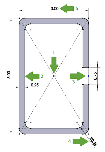
Key features of the profile pictured above
- Origin location. This location is the default spot that the SOLIDWORKS weldment profile will align with the member length. Weldment profiles can be repositioned relative to the member length; however, this is the initial location where it’ll be positioned.
- Orientation. The profile is taller than it is wide. This means that its default orientation will keep the longer sides vertical, which are stronger in bending than the short sides at the top or bottom.
- Placement of the channel. The channel is placed along the tall right side of the profile. This means that this side is weaker than the opposing side. In addition, channels like this are created for items to slide within the member like a track, so choosing the side for the gap changes what can fit inside and slide along the length of the weldment member.
- Rounded corners. The sizes of these corners change how the tubing is manufactured. Tight radii require different tooling devices than large radii. In addition, you want to determine if corners will interact with other solid objects. For example, a lumber rack on a truck is going to have lumber, metal piping, heavy power equipment, and many other objects that can potentially scratch, chip, and dent the weldment structure. Adding corners of the right size can minimize damage and wear over time on the finished product.
- Dimensioning. Weldment profiles are typically identified by their outer dimensions. Therefore, you typically want to dimension the profiles using the outer sketch elements. In this case, the dimensions for height and width include the rounded corners. The channel on the right side is also specified by its total width.
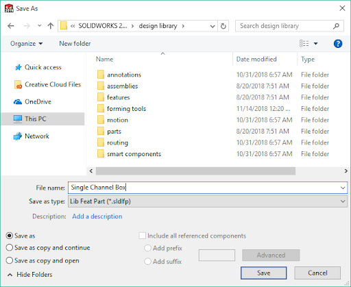
How to properly save a profile
- Select the sketch in the FeatureManager Design Tree.
- Select Save As.
- Select Library Feature Part from the file type drop-down menu.
- Select Save.
This will create the correct file type, which is indicated by the sketch icon changing in the SOLIDWORKS interface.
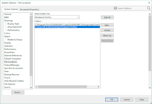
How to properly create a folder structure for the profile
It’s also important to create the right folder structure when you’re saving a profile. Because the PropertyManager in SOLIDWORKS has two levels of subfolders created to contain any weldment profiles, any custom folder you set up needs to also include two levels of subfolders.
- Set the SOLIDWORKS file path to look in the location where you’re creating your profiles.
- To do this, go to System Options.
- Change the “Show folders for” drop-down menu to Weldment Profiles.
- Select the Add button.
- Select the top level folder where you’re saving the profiles.
- Once you have that folder selected in SOLIDWORKS, create two subfolders. (In this case, I’ve created the main folder called “Weldment Profiles” with subfolder level one called Custom Profiles for the weldment Standard and a second subfolder called Single Channel Box for the weldment Type. The custom profile is saved in this second sub-folder called Single Channel Box in this example.)
- From here, you can use the profile to create weldment profiles!
How to apply the weldment profile to your Design
Once your custom SOLIDWORKS weldment profiles are defined and saved in the right location, you can apply it to your design to create the structure. Simply choose the profile in the PropertyManager, and then begin selecting members in a single group that falls within a 2D plane. This means that you’ll create additional members by adding more groups in the PropertyManager.
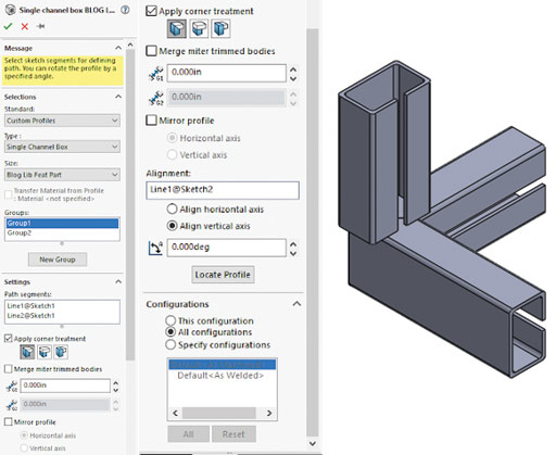
Once you’ve created all the members, make sure the orientation is set properly. To do this, use the Alignment selection box. You can select sketch entities to change the way in which each member is oriented. The sketch entity selected will align with the upward direction of the original SOLIDWORKS weldment profiles.
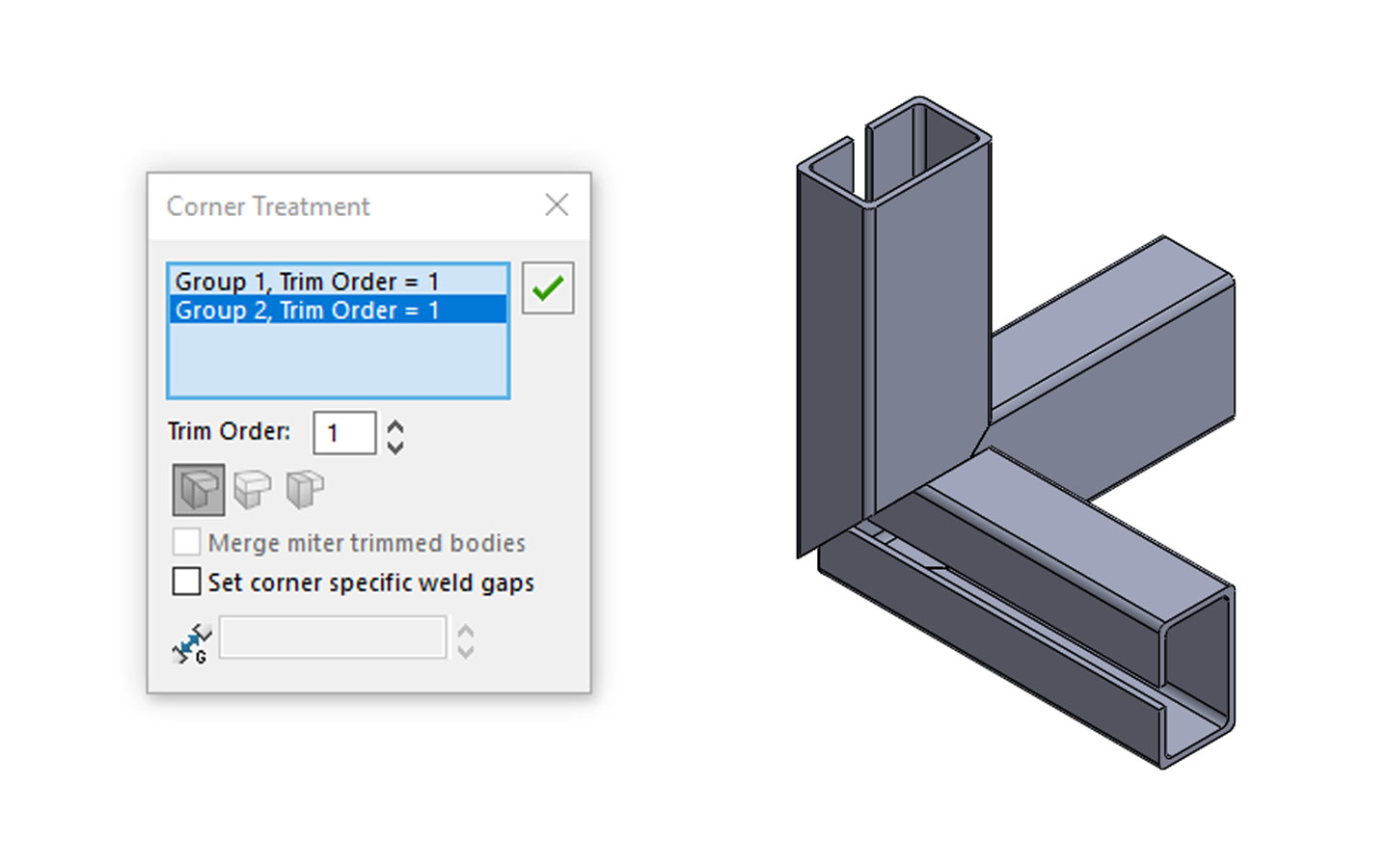
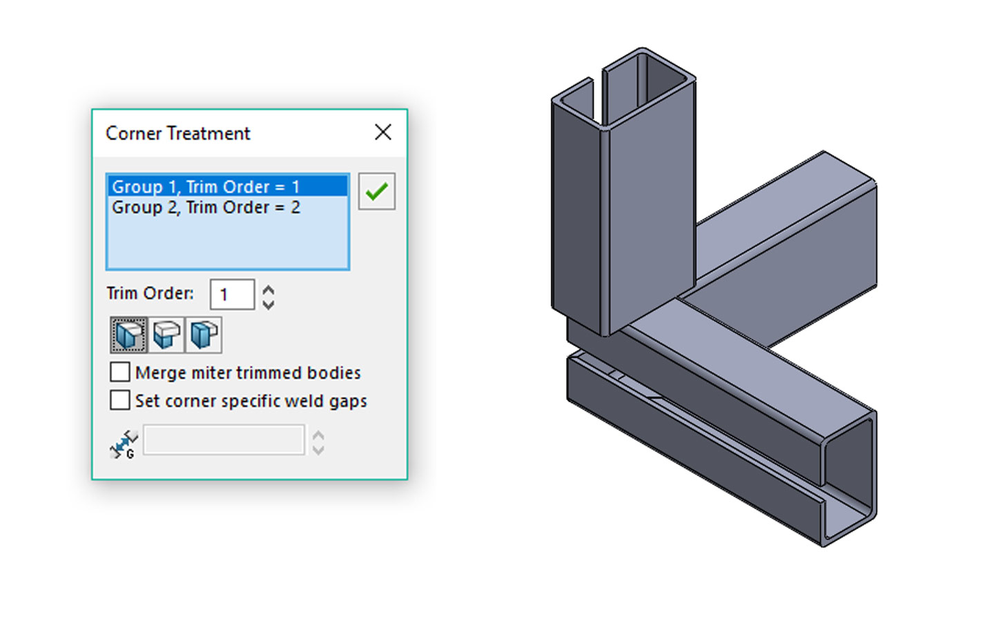
The major impact of orientation is not only how they’re positioned along the lengths of the members, but also how the corners connect and how they can be welded and secured. There are multiple ways in which you can set the corner options. Just click on the colored dot where they’re connected, and then set the different priority levels for each member. Setting them equal means they’ll all be cut at their common intersection points, while setting a member at a lower priority levels means it will be cut by the other members set higher.
With all the members set, you can make modifications to the weldment profile and the entire model will adjust accordingly. This is the beauty of parametric modeling based on a single profile. This can be as simple as changing a dimension or adding filleted corners instead of sharp ones. Customizing your SOLIDWORKS weldment profiles gives you a lot of control over your design and will help you craft your structures exactly the way you intended.


